It is quite easy to listen to a conversation on a land line:
Let’s quickly go over how a land line works:
- There is a 48V DC with around 2kV series resistance on the phone lines that are called Tip and Ring
- When ringing, an AC voltage of around 65Vrms 20Hz is sent over your phone line. Typically the ringing cycle is On for 2 second and Off for 5 seconds.
- When your phone detects the ringing voltage it starts ringing and when you pick it up, or when you pick up the phone to make a call, your phone places a load of around 390 Ohm on the phone line. This load pulls the line voltage down by drawing current. The switching center detects this drop and knows your phone is off hook. If you were ringed, then the center establishes communication. But if you picked the phone to call, the center sends you the dial tone.
- When you are ringed, after the first ringing signal the center transmits caller ID data digitally to your phone which the phone usually displays on a LCD screen.
- The audio signal is an uncoded plain AC signal.
- When you dial, you either use:
- Pulse dialing (old style in rotary phones) which is basically quickly shorting and opening the tip and ring wires equal to the number you want to dial (10 shorts for 0), with a longer pause between the numbers.
- Tone dialing which is basically two audio sine waves super imposed, and indicate a single number depending on the frequency of tones. Switching centers accept both methods above.
- When you turn off the call, the line voltage jumps back up to 48V which indicates to the center that the call is finished.
- When you talk or being talked to, both audio signals are superimposed on the same line. There are filters in your phone to subtract your voice from the two signals so you can hear the incoming voice easily. Although a perfect subtraction is not needed as you are already hearing your voice through air.
- The audio frequency is filtered below 4kHz.
So basically listening to a call is quite simple. Like I said in the video, during an active call you don’t need to care for much. The line voltage is low (around 7V) and all you need is to isolate the DC using a capacitor and send the AC signal to a head set. The headsets typically have around 32 Ohm resistance per side. If you connect the line to both sides, it will load and attenuate the AC level more.
In active call, having a series single 100uF and >10V capacitor is enough to isolate the DC and send all frequencies into the head set, like below:

Single Capacitor Wiretapping
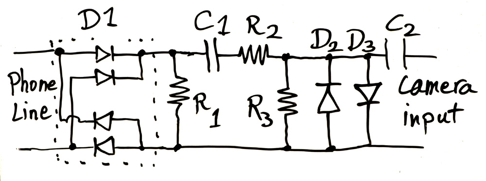
But you can’t just rely on a single capacitor to handle all protection and save your audio input, which in my case is my precious camera! The lines can have any polarity, the ringing voltage and the idle DC voltage are huge. And so I designed the circuit below:

Wiretapping Circuit
Let me explain how it works.
- D1 is the FULL BRIDGE RECTIFIER! We need this to make sure no matter what the order of the wires are, we send the right side up DC voltage into the circuit. Puny single diode wouldn’t work here, because then the circuit would not work and will be off if the DC voltage is in reverse.
- The rectifier is typically used to make a DC voltage, but here we don’t want to rectify, we want the AC signal of the audio to go through. And that’s where R1 comes into effect. The diode D1 only outputs current one way which would charge C1 up to the maximum of the AC + DC signal. And so for any voltage below these when AC level goes into falling cycle or DC level drops for some reason, the diode turns off and the AC signal is cut off from the circuit. R1 makes sure C1 is discharged as the AC signal goes down and so the entire AC cycle goes through.
- But what is C1 for? It is of course to isolate the phone line’s DC voltage from the circuit and to only let the AC through.
- Then the AC signal goes through the R2 / R3 resistor divider, which in my case I divided the signal by a factor of ~3. Because per my measurement, the AC signal was a maximum of 3V peak to peak, or 1.5V amplitude. Dividing it by 3 would give me a 0.5V maximum peak for the signal. This would ensure that the AC is not distorted by my next stage, D2 and D3 diodes.
- D2 and D3 diodes are there to limit the AC peak level. For positive peaks above ~0.6V, D3 would conduct and clamp the voltage to around 0.6V to 0.7V, and for negative voltages, D2 would do the same. This way the AC amplitude wouldn’t rise above 0.7V peak, which would be safe for my camera input. And again this is why I divided the AC signal using R2 and R3 to have a maximum of 0.5V audio level, so that D2 and D3 won’t clamp and distort the audio. Basically D2 and D3 would clamp the ringing voltage, as well as any transients and ESD voltages coming in. Of course their clamping current is heavily limited through R2.
- And last but not the list, C2 isolates the DC voltage coming from the camera from the circuit which has a 0V DC. My camera outputs around 2V DC when recording, which would easily be clamped to 0.7V by D3 and pretty much destroys the AC audio signal too. But with C2, no clamping happens. The DC coming from the camera is to power electret microphones, and sometimes is also used as an indication by some microphones attached to the camera so they can detect when the camera is recording and wake up.
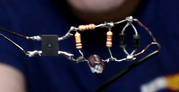
You see in my circuit below (before I added the C2 capacitor) I have moved the location of C1 to the bottom side, solely to make the circuit look more symmetrical. C1 is a series capacitor with the rest of the circuit anyway, and switching locations of series components will not affect the properties of the circuit.

Now you might like to know what are the proper values for these components. I can tell you the values I used which I picked based on feeling and what I had available that worked well, which are:
- A full bridge rectifier chip with not much current capability. I don’t have its part number, it is under the hot glue now! But any generic bridge would work.
- R1: 10kOhm
- C1: 1uF 50V (mind the polarity, must withstand the 48V DC)
- R2: 2.2kOhm
- R3: 1.2kOhm
- D2 and D3: Any generic all purpose rectifier diode, but I used 1N4001. Others like 1N400x (x=1 to 7) or 1N4148 or similar would work just fine.
- C2: 10uF 16V (mind the polarity)
Design Tips:
- To make sure you are passing low frequencies well enough, C1 x (R2 + R3) should be large enough as the circuit is a high pass filter. For example if the low frequency role-off is f = 100Hz, then f = 1/(2 x Pi x C1 x (R2 + R3)) would help you calculate. In my case R2 + R3 = ~3k. So C1 = 0.53uF and above would be fine. My value of 1uF seems pretty good here.
- R1 should draw the same or more current than that C1 was charged with during positive peak of AC signal. More current is fine, because the voltage across R1 only drops to a point where D1 turns on which results in C1 voltage following the AC input. The excess current is provided through the diode from input rather than discharging C1. But a smaller R1 current would be trouble, because then C1 would continue charging up and turning D1 off, clipping the AC input like a real DC rectifier. I guess some white board explanation would be good at this point! But anyway in my circuit if AC signal is at its maximum of 1.5V peak, this voltage over (R2 +R3) = 3k will result in 0.5mA charging C1. So we need more that that current through R1 to ensure C1 discharges properly without creating DC offset. We already have a 7.5V DC on phone line, which plus the 1.5V positive peak of the AC results in 9V. This voltage through the D1 diodes drops back to ~ 7.5V DC. 7.5V divided by our R1 of 10k would be 0.75mA, over the 0.5mA we need to properly discharge C1. Hey, my feeling was pretty on point there!
- Increasing C1 would help passing low frequencies better, but wouldn’t effect the charge/discharge current and so resistor values won’t need to adjust.
- C2 doesn’t need to be much. A value equal to C1 or more is fine because of high resistance input of the camera audio jack. But of course I don’t have an accurate measure if how much that input resistance is. If known, then C2 should be calculated better. Otherwise keep C2 a bit higher. If you are happy with your audio quality, then it is fine.
