How does human body react to AC versus DC at high voltages? Watch the video below:
Don’t try to touch any sort of high voltage yourself of course, you may die if you know what I mean!
The experiment clearly shows that AC is much more hurtful and dangerous than DC voltage. Like I mentioned the capacitive property of body makes it way more conductive towards AC current. A capacitor’s impedance is proportional to reverse of frequency and drops as the frequency is increased. But at zero the capacitive impedance is equal to infinity, which leaves the body resistance that can be around 100 kOhm over dry skin, or much smaller across tissues under the skin. And that’s why AC is much more dangerous than DC.
In fact based on Wikipedia where I get most of my knowledge from, an AC voltage of below 50VAC is considered extra low voltage, while a DC level below 120VDC is considered extra low voltage. That confirms the more dangerous nature of AC.
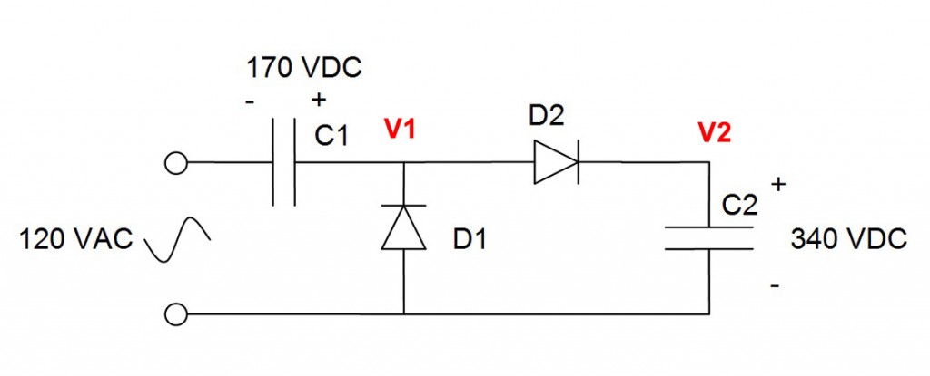
Now let me explain to you how the circuit I made works. Below is the schematic again:
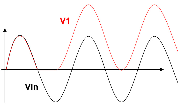
 This is some sort of booster circuit. The first stage consists of C1 and D1 that work together to create a DC shift on the AC signal input. If you look at the plot below you will see the AC input as the black line. When the input rises, D1 is off as it is reverse polarity biased and the capacitor acts like a short for AC and so V1 will follow the input. But as the input tries to go negative and pull V1 down with it, it will forward bias D1 and will turn it on.
When D1 turns on, it will clamp V1 close to zero, or more accurately -0.7V for a regular diode. But the input voltage keeps going down. This means that a current will run through C1 and D1 that will charge C1 close to the peak of the AC signal, which in my case was close to 170VDC.
Remember that a 120VAC has a peak of 170V. 120VAC is the effective voltage, or root mean square value.
Now when the AC signal reaches its minimum at the negative peak, it will try to rise at which point the current through D1 flips and turns D1 off. So now again the charged capacitor acts as an AC short and rises all the way up to the positive peak, which added to the charge on the capacitor, will add up to twice the amplitude of the AC signal or in my case, 2 x 170V = ~340VDC.
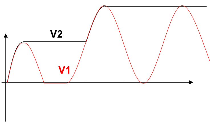
Now the second part of the circuit which is C2 and D2 is basically a peak detector, or a peak hold circuit. C2 is initially not charged. Every time V1 rises above C2, D2 is forward biased and turns on, current flows into C2 and charges it up. And every time V1 drops, the current flips that turns D2 off and so C2 will just hold its voltage.
 So V2 will end up being charged to a DC level almost double the AC signal amplitude. Of course this is considering no load on the voltages, and also there is some voltage drop over the diodes. With loads, the voltages will drop.
This circuit can be repeated and cascaded to create even higher voltage. Every similar circuit will add the equivalent of the AC signal peak to peak voltage to the output. I’ll leave it to you to figure out how to cascade it.
Just remember to rate your capacitor properly and don’t connect them backwards. And don’t mess with any high voltages!

