I designed a circuit so I could make my oneTesla Tesla coil make sounds with my voice:
Well as you saw in the video, typical Tesla coils like oneTesla generate sound and music by interrupting the output arcs at a given frequency, usually programmed by a micro controller. If you like to see my videos on oneTesla and how it works, here they are:
- How to Solder (OneTesla): https://youtu.be/f2biiEgIsF0
- All you need to know about Tesla Coil: https://youtu.be/Og9j5Wk0Di4
In my case the micro controller was outputting pulses between 14uS to 54uS. The wider the pulses, the longer the arc and so the louder the sound.
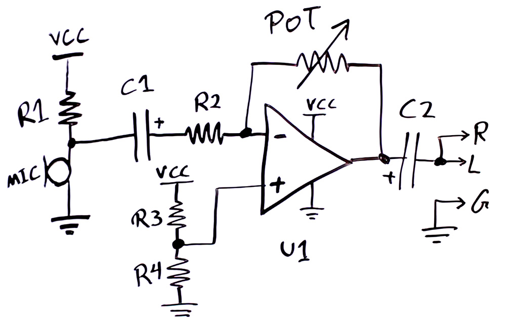
So what I did was to replace that signal with my own. I used a regular electrec microphone and fed it into the amplifier circuit I had designed before for my Wireless Lavalier circuit. The circuit I used as amplifier looks like below. See that page for component details.

As I found out later, my circuit is susceptible to electromagnetic noise from the Tesla coil output. If you have designed a circuit for consumer use, you would know battling EMI (Electromagnetic Interference) can be a very hard task to do. But SPRINKLE CAPACITORS everywhere you shall be fine, if you are lucky!
What I would do is to add capacitors, one parallel to MIC (let’s call it C3) on the board side of the wire to get rid of noise picked by the microphone wire, one parallel to R4 (C4) and another parallel to POT (C5). C4 can be large. For high frequency 100nF could be enough, and if EMI still sucks then maybe another 10nF in parallel to C4. But for C3 and C5 you need to consider the audio frequency and make sure you don’t filter it much and ruin your audio frequency response. For C3 don’t go above 10nF and for C5 no more than 200pF (in case of my circuit, other circuits have different properties).
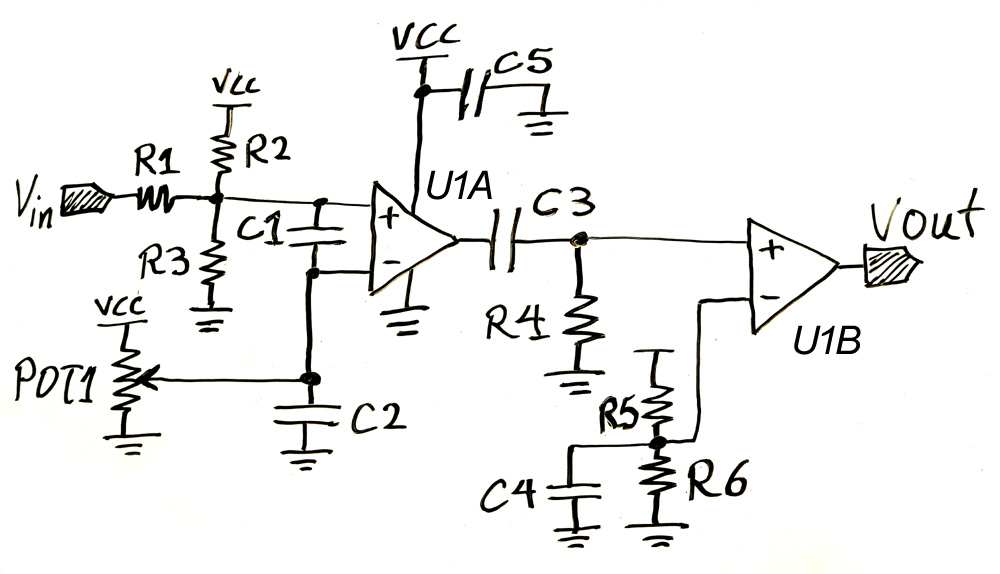
And then I fed the output of the amplifier into the circuit below.

Here’s what every component does:
- R2 and R3 provide a DC bias of around 1V that the audio input will ride on.
- R1 combined to C1 provide signal filtering to prevent high frequency to get in.
- POT1 provides a threshold voltage that the audio + DC bias input will be compared to by the U1A comparator. If the input signal is above the threshold, U1A output is high and otherwise low. The closer the POT1 threshold voltage is to the DC bias created by R2 and R3, the more sensitive the circuit becomes, and U1A can trigger on noise if they are too close.
- C2 is to filter noises on POT1 threshold voltage.
- U1A creates square wave output.
- C3 and R4 are a high pass filter and only send out the edges of the C3 input square wave and C3 output always discharges at a fixed rate determined by the time constant RxC.
- R5 and R6 create a fixed voltage around 1V filtered by C4, which the pulses are compared to.
- U1B cleans up the input pulses into nice looking square pulses.
- C5 is to filter noises on the power supply.
- The entire circuit is powered from the output of the 5V regulator on the interrupted board.
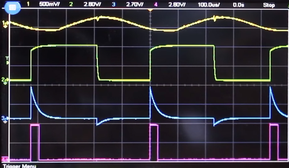
And so below are the waveforms through this circuit. From the top, we have the sinewave input, U1A output, C3 output, and U1B output.

Below are the component values:
- R1 = 3.3k Ohm
- R2 = R5 = 82k Ohm
- R3 = R6 = 18k Ohm
- C1 = C3 = 100nF
- POT1 = 100kOhm
- C2 = C4 = C5 = 10uF
- U1A and U1B are in one chip MCP6562. But any comparator with push-pull output with proper frequency band (over 1MHz) would do.
- R4 = 180 Ohm (for around 30uS pulse) You could use a potentiometer to trim as you wish.
If EMI is still an issue smaller capacitors like 100nF parallel to the 10uF capacitors should help. Remember each capacitor has an operational bandwidth and won’t filter well above that frequency. The higher the capacitance the lower the functional frequency. That’s why we put smaller capacitors parallel to larger ones, to increase the filtering capability to higher frequencies.
