This circuit is made as a part of my video in which I wanted to make a wireless lavalier microphone:
Well that wireless thing didn’t work as I expected, but at least I could make the microphone work!
Condenser microphones need to be powered, because they act like a variable impedance (usually capacitance). To capture a changing impedance, the easiest way is to run some current through it (usually using a series pull up resistor) and then capture the changing voltage when the impedance changes.
Of course the voltage signal directly from the microphone is not very large and usually requires amplification. And that’s why I designed the following two different amplifier circuits:

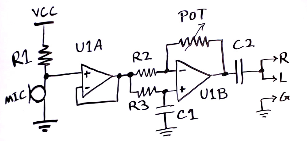
Figure 1: Amplifier with Buffer
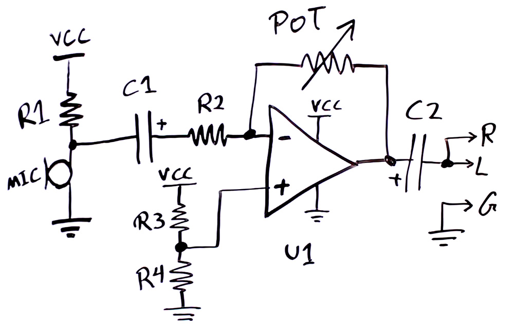
 Figure 2: Amplifier without Buffer
In both circuits I used TLV4112 operational amplifier which has two OpAmps and a rail to rail output for maximum voltage swing, and works down to 2.5V supply so I can run it using two AA batteries or VCC = 3V.
In Figure 1, the signal from microphone goes through a buffer (U1A) first which prevents loading the microphone signal, and then goes through U1B amplifier circuit. Since the microphone signal is riding on a DC voltage, the same voltage is filtered through RC filter R3 and C1 and provided as reference for U1B amplifier. The gain of the amplifier if equal to Vo/Vi = -(pot/R2) . So changing potentiometer value would adjust the gain.
The output of the amplifier also rides on the same DC voltage level as microphone signal. To pass the signal to a microphone input jack this DC voltage should be removed as done by C2 capacitor.
The downside of this circuit is that because a buffer is used, and every amplifier has some internal noise, that noise is added to the signal and is amplified. But in return the microphone signal level is not affected by the gain stage loading it.
The component values for this circuit are:
- R1 = 6.8k
- R2 = 1K
- R3 = 100K
- POT = 100K
- C1 = C2 = 10uF
Figure 2 amplifier works very much the same as the first design. Except that the amplifier has a separate reference voltage made by R3 and R4, and there is no buffer.
Due to the lack of buffer, the signal from the microphone is loaded to a smaller level which is then amplified. But it can be less noisy as the buffer is removed. The component values are:
- R1 = 6.8K
- R2, R3, R4 = 1K
- POT = 100K
- C1, C2 = 10uF
Other Considerations:
In general human ear is very sensitive to noise and can hear it easily and it is hard to completely get rid of noise. Amplifiers have a lot of internal components that add to the noise level. So selecting a very good low noise amplifier is crucial for a high performance circuit. Make sure to check the datasheet and pick a low noise OpAmp.
For small signals, it can be beneficial to amplify the signal with a single class A transistor circuit like THIS to a decent level and then amplify further with an OpAmp. A single transistor poses less noise on the signal. But the gain should be kept small, because a high voltage output also results in larger distortion.
Doing all amplification through low noise discrete circuit can also be a good solution. But I like OpAmps, they keep the design simple!
It is important that the power supply of the circuit is very clean. So using proper filtering on the supply to isolate this circuit from noisy circuit and sources is recommended. Especially if the circuit is placed close to RF transmitter circuits that can also radiate to the analog circuit. In such case, you might like to sprinkle more capacitors here and there!

Pingback: Trying to Make a Wireless Lavalier Microphone – Viral Videos
Very interesting.
Very informative.
I recently had an idea, what if I could make a USB to audio jack adapter. Will that work? I can plug the USB microphone into the camera directly…
Cool article
what will be the circuit if we have a dynamic microphone
Dynamic microphones generate a small voltage on their output, so I’d imagine just some kind of differential amplifier with a filter to help with high-frequency noise.
Is this circuit viable using large diaphragm capsule?
Nice i added your nice page my pinterest board https://www.pinterest.com/diygearweek/best-diy-audio-gears-intruments-design/
Hi colleagues, pleasant post and nice urging commented here, I am genuinely enjoying by these.
Pingback: Changing Signals into Pulses, to Drive the Tesla Coil | ElectroBoom
NOICEEEE!!!!
Very Informative
grgrgr
nice
Very Informative article, Amazing article. I am so impressed.
nice article
Hi there to every body, it’s my first go to see
of this website; this blog includes remarkable and genuinely good stuff for readers.
What is the mic that you’re using at https://youtu.be/fO8pPjlFtNw?t=18s ?
It’s an awesome post in support of all the web visitors; they will take
advantage from it I am sure.
I delight in, lead to I discovered exactly what I used to be
having a look for. You’ve ended my four day lengthy hunt!
God Bless you man. Have a nice day. Bye
Sir! You must review with ergency before the world believes this! https://www.goodnewsnetwork.org/generator-that-creates-electricity-from-gravity-could-revolutionize-renewable-energy/
Okay, I have 2 questions.
What’s the difference between a Zener Diode and a Regular Diode?
Why are Zener Diodes never used in a “FULL BRIDGE RECTIFIER!!!!!”
Regards,
Jerry
Which gives repealing shock ac or dc????
Therw are multiple startups on RF wireless power using phased array or just a single antenna. Can you make a video and explain if they are fraud or the future?
:-) x
I think I can test it with my raspberrypi and burn it …….
Can you do a video on emp gun?
Found one here: https://youtu.be/JvpZXmYRP4o
But I lot of comments say its fake. Also, it doesn’t explain anything about its electronics. It’ll be helpful if we see your take on it. Thanks.
Hi there—sorry my comment is unrelated. I’m interested in talking to you privately. I’m that girl who survived being electrocuted in the pool you were contacted about last year. Shannon_colhoun@yahoo.com
Please get in touch;)
Pingback: Trying to Make a Wireless Lavalier Microphone
I feel it is important electroboom that you know the dangerous effects of vacuumed tubes and electisity, it tends it creat X-rays ( hint hint you resent video with the light tubes.)
The secondary of a Tesla should not be bad,but more concerning is the primary
Find this info in the “Ultimate tesla coil design” Book
do you research!!!!
P.S CRT tubs could be cool to see on you vedieos but don’t forget the phosphorus
hi, I am a fan of u in China. I am studying electronic which is my major in Wuhan university. I love ur viedo and ur viedo really inspired me in my study, I just wanna say Thanks! and hope you can reply me which will cheer me up.
——Hunterlee, 20years old boy from China
Hello, I’m also in Wuhan University and my major is Communication Engineering. And I’m junior. ( ̄▽ ̄)~*
Can you do a vedieo with a shock gag pen that you give to your friends to zap and prank them with plz
Really Like the videos bro..
Want can u do with old cell phones
And their cameras .
Thanks! I’m going to test this circuit with a piezo hydrophone.
I finally understood OpAMPS and how they amplify a signal, this was such a headache in electronics course. Thanks, Magdy.
I would like to ask if there is any better than mic4452 mosfet driver chip I think mic4452 lack of driving force
“Totem” driver, made of a pair of high-frequency and medium-power transistors, e.g. D882/B772 or, much more powerful, TIP41C/TIP42C. I used them in my Tesla coil’s GDT driving circuit. They’re powerful enough to drive IGBT modules.