AC hurts more than DC because of human body capacitance. But how big is this capacitance?
So there are multiple ways to measure capacitance, which I should say measuring current through a capacitor is not one of my favorites. Especially when it comes to measuring human body capacitance. But there are two more ways, both of which include placing a series resistor to the capacitor:
- Supply a square wave to the series resistor with other end of capacitor at ground. Measure the voltage across capacitor on a scope and see the exponential rise/fall of the voltage and calculate the capacitance.
- Supply a sinusoidal (sine) wave to the resistor and scope the output waveform and measure the delay between output and input and calculate capacitance.
I personally like the second method because the entire output wave shifts with the same delay. All you need to do is to compare the zero crossing of the input and output waves to find the delay. This can be easily made into a digital capacitance meter.
Capacitors resist against changes in voltage. When a series resistor is between the supply and a capacitor, capacitor causes a delay in output voltage and reduce its amplitude.
Human body have both a resistance and a capacitance in parallel. When a DC voltage is applied across body, only body resistance sends current through while for AC, it is both resistance and capacitance.
As shown in the following schematic, a series resistor is placed between supple (Vin) and body, which is called Rsource.
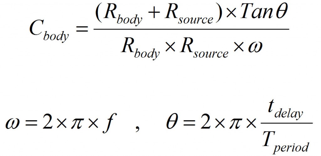
Now as you saw in the video, probing both Vin and Vout, you can measure the delay and calculate the capacitance using the following formula.
Cbody and Rbody are human body capacitance and resistance. You can measure the resistance using a multimeter. I measured my resistance over dry skin to be close to 1M Ohm. Different skin conditions changes this resistance.
Rsource is the series resistance you put between supply and body. You should choose this resistance properly to obtain proper accuracy. I used 100kOhm for frequencies of 100Hz and below, and 10kOhm for frequencies above 100Hz to 10kHz. To achieve more accurate results, it is good to keep the delay around 10% of the waveform period.
f in the above formula is the supply frequency, Tperiod = 1/f and tdelay is the measured delay between input and output waveforms.
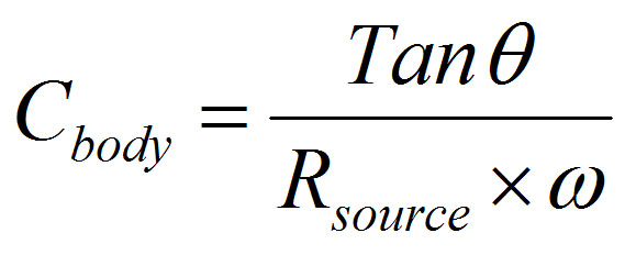
For my measurements since my body resistance was close to 1M Ohm, I assumed Rbody >> Rsource, in which case you can simplify the formula as below:
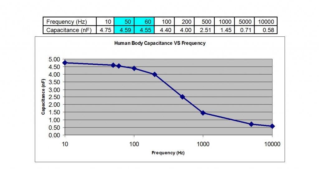
And so using this method, I measured my body capacitance at different frequencies which followed the following results:
The capacitance at 60Hz North American power line frequency is not huge. But the capacitor impedance is around 580 kOhm which in parallel to the 1M Ohm body resistance, it will result in around 500 kOhm total impedance. (you need to know how to calculate parallel/series impedance for this one).
So this means, for DC voltage you have 1M Ohm impedance (made of just resistance) while for 60Hz AC, you have 500 kOhm. So for some AC RMS value, the current through body is double compared to the same level DC voltage. and THAT’s why AC hurts way more than DC at the same level.
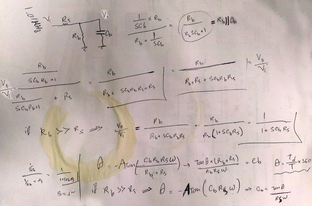
If you like to know how I come up with the formulas I showed above, following image shows my calculations.


MU Dai Thien Su H5 NV Cung Thu https://www.youtube.com/watch?v=9q0pbjlef74
Excellent video.
Bonjour,
Existe t-il sur internet pour une tension 9V quelque soit la forme de l’onde, une courbe indiquant les seuils de courant dangereux en fonction de la fréquence pour la gamme 1 Hz et 100Khz ?
Nathan
Haha. Great video.
I am now a fan.
That is really interesting. I experiemented with different DC voltages on my hand from 30 to 300 V. Up to 120 V I don´t feel anything or only a little pinch on my finger. As I go up tp 270 V, depending on my resistance at that time, I may feel nothing up to 290 V or get quite a shock at 130/150 V already. With AC I can already feel it at 20 V as much as with 150 V (earliest) it is around 3 mA I guess. What I noticed and intrigued me is that in the evening my resistance tends to be lower allowing me to go up to 280 V while during the day I can´t. I dont know exactly why.
Hi, excelent videos! Please, check calculations of figure “Formula to calculate capacitance, using measured delay” – I believe that equation for the phase angle theta stands for Rbody, Rsource and Cbody all in paralel.
Pingback: Electricity Pain verus Frequency | ElectroBoom
Hi Mehdi,
What you said about “Capacitance changes as the frequency changes” I don’t think it is quite right. Here’s why:
An electrolytic capacitor, for example, has constant capacitance regardless of the input freqeuncy since C=Q/V. But what changes is its capacitive reactance. As the frequency goes up, the capacitive reactance goes down and vice versa. The actual capacitance stays the same. Xc= -1/2piFC This Xc is in parallel with your body resistance, therefore reducing the total resistance and allowing more current to flow.
Please explain.
The thing is that ideal capacitance remains unchanged. We know that capacitance is dependent on many factors like plate dimensions and distance as well as dielectric properties. Of course dielectric plays a big role. For example its properties can change by bias voltage or frequency. I was at a seminar where they explained the capacitance value for some types (Y5V being the worst, I will never use that again) change based on DC voltage across it. When you are at the rated voltage, the capacitance can be reduced to half. Same goes for electrolytic or ceramic type.
Also you know when a capacitor is charged, the plates attract each other and pull towards each other. If electrolytic material is soft, it can be squished and the capacitance increase. Ceramic material has piezo properties, means that when electricity is applied to it, it deforms. That’s why ceramic capacitors can make a buzzing sound when audible frequency is applied across them. For the same reason their value may change slightly based on frequency.
Also all capacitors have parasitic components in them, like series/parallel resistors and series inductor. So if you measure across a certain capacitor, and try to calculate its capacitance assuming it is a capacitor alone, you will see its value changing based on frequency. So you can’t assume your component is a fixed capacitor for all variables imposed to it.
So some capacitors will actually change capacitance depending on the dielectric, plate size, etc.. interesting.
So what changes in your body capacitor as the frequency increases?
Hey Mehdi,
Is that a coffee stain or an orange juice stain on your scratch paper? Also, it looks like there is some really cool circuit diagrams on the other side of the paper, but I can’t make them out. Is that a nifty something you’re cooking up for a later video?!
~Brandon
That’s a coffee cop stain. I don’t remember what I was cooking on the back side, but either for work or video!
Hey Mehdi. I’ve been a big fan of your channel and have been subtitling your videos into Chinese for some time. But now I have two questions (one on behalf of your Chinese fans):
1. I notice you are using different resistors for different frequencies. Is it because your circuit has, as I recall, cutoff frequencies? I wonder how this may affect the measurement’s accuracy if we use the same resistor for all the frequencies.
2. And how’s your high power Tesla coil project going now?
Thanks a lot and keep up for your good works
1) Like you said, it is related to cut off frequency. The cut off frequency is where the phase starts to shift. So you have to change the resistor to make this shift happen at different frequencies
2) The high power Tesla coil is in process. Those projects are harder to design and build. Stay tuned!
Say hello to my Chinese fans!
Thank you so much! Will do.